This Help topic provides instructions for configuring load balancing in your NAC environment. Load balancing allows you to evenly distribute authentication requests and switch configuration ownership among your NAC gateway appliances. This can be useful in NAC deployments with a large number of switches, where manual delegation of switch resources would be cumbersome.
Load balancing is configured at the appliance group level. Once configured, all the NAC gateway appliances and switches in that group will participate in the load balancing process.
NAC Manager provides two different load balancing configuration options: either ExtremeXOS/EOS firmware on S-Series and K-Series devices, or utilizing external load balancers.
Instructions for:
ExtremeXOS/EOS Firmware Load Balancing
Use the following steps to configure the native RADIUS load-balancing functionality on S-Series and K-Series switches.
- Select an appliance group in the left-panel tree and click on the right-panel Configuration tab.
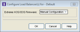
- Click on the Edit button in the ExtremeXOS/EOS Firmware field. The Configure Load Balancer(s) window opens.

- Select from the following four options:
- Manual Configuration – Select this option if you have manually configured load balancing on your switches using the CLI. The Manual Configuration option will leave the value as set on the device unchanged.
- Standard – Specifies that the primary RADIUS server should always be used for authentication, if it is available. The standard RADIUS authentication algorithm focuses on using RADIUS servers for redundancy rather than for scale provisioning. The only time secondary RADIUS servers are used, is when the primary server is unreachable.
- Round Robin – The round-robin RADIUS authentication algorithm spreads authentication requests evenly between available RADIUS servers, allowing large numbers of authentication requests to be evenly distributed across all RADIUS servers. This allows for a maximum authentication throughput for the number of RADIUS servers configured. Additionally, if a single server is down, incoming authentication sessions will be unaffected by the outage and will be distributed among the remaining available RADIUS servers.
- Sticky Round Robin – This algorithm uses round-robin when assigning a RADIUS server to each unique authentication session, but specifies that the same RADIUS server should be used for any given authentication session once a session is initiated. In large-scale NAC deployments, this algorithm is used for switches that are authenticating more users than a NAC appliance supports. For example, a NAC deployment might have an S-Series device that supports 9000 users deployed at the distribution level and authenticating users to three NAC appliances that support 3000 users each. In this scenario, the sticky round-robin algorithm allows the S-Series or K-Series device to spread the load across all three NAC appliances while using the same NAC appliance for all RADIUS transactions for a given session (MAC address).
NOTE: If you are load balancing more than two NAC appliances, go to Tools > Options > Display > Display Counts and increase the number of NAC gateways a switch can be assigned to in the Switches tab. - Manual Configuration – Select this option if you have manually configured load balancing on your switches using the CLI. The Manual Configuration option will leave the value as set on the device unchanged.
- Enforce all the appliances in the appliance group.
To disable load balancing, access the Configuration tab for an appliance group, and set the Load Balancing mode to Standard. Enforce all the appliances in the appliance group.
External Load Balancers
This section describes how to configure an ordered list of external load balancers that will be used to evenly distribute authentication load across multiple NAC appliances.
Typically, there is a primary and secondary (backup) load balancer configured to load balance the RADIUS requests for all the switches in an appliance group.
When an enforce is performed, the NetSight server assigns virtual IPs (VIPs) to the primary and secondary load balancers. Each switch in the appliance group will send authentication requests to the primary VIP, which will load balance authentication requests between the available NAC appliance gateways in the appliance group.
When a load balancer receives a RADIUS authentication request from a switch, it determines which appliance will service the request based on various criteria such as current appliance load, availability, and response time.
Use the following steps to configure load balancing:
- Perform the following preliminary steps:
- Verify that your NAC gateway appliances and switches (NAC RADIUS clients) are not on the same subnet. Appliances and switches cannot be on the same subnet for load balancing to work, as RADIUS access-request and response packets must traverse the load balancer for proper operation.
- Configure your load balancers to load balance port 1812 for authentication and port 1813 for RADIUS accounting.
- For 802.1x authentication, set the load balancers to sticky mode based on the source IP of the authentication request (the switch's IP address). This ensures that all RADIUS packets in the 802.1x authentication are sent to the same NAC appliance.
- Select an appliance group in the left-panel tree and click on the right-panel Configuration tab.
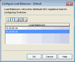
- Click on the Edit button in the External Load Balancing field. The Configure Load Balancers window opens.

-
Use the toolbar icons to configure an ordered list of load balancers.
- Click on
 to open a window where you can add an IP address for a new load balancer. Click OK.
 - Add all of your RADIUS authentication and accounting load balance IPs to the list.
- Use the up and down arrows
 to configure load balancer precedence in the list. All switch traffic is sent to the first load balancer in the list, unless that load balancer is down. Then the traffic will be sent to the second load balancer in the list, and so on.
 - When your list is complete, click OK to close the Configure Load Balancers window.
- Enforce all the appliances in the appliance group.
- Click on
To disable load balancing, remove all the switches from the appliance group and then disable load balancing on the appliance group's Configuration tab.
External Load Balancing Example
This example demonstrates how load balancing works for an appliance group using one load balancer with the IP address of 10.22.70.1. The appliance group has five NAC gateway appliances and eight switches.
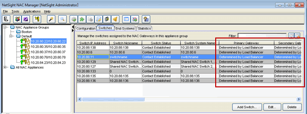
All switches in the appliance group will appear against each NAC gateway in the group, as shown in the Switches tab below. The primary, secondary, tertiary, and quaternary gateway columns in the Switches tab will indicate that the load balancer will determine the gateway.

At Enforce, the configuration for all eight switches is written to all five gateways. The table below shows how load balancing will be configured for all the gateways.
| Switch IP | Primary Gateway |
Secondary Gateway |
Tertiary Gateway |
Quaternary Gateway |
|---|---|---|---|---|
| 10.20.88.127 | 10.20.80.22 | 10.20.80.35 | 10.20.80.37 | 10.20.80.78 |
| 10.20.88.129 | 10.20.80.35 | 10.20.80.37 | 10.20.80.78 | 10.20.80.23 |
| 10.20.88.6 | 10.20.80.37 | 10.20.80.78 | 10.20.80.23 | 10.20.80.22 |
| 10.20.88.11 | 10.20.80.78 | 10.20.80.23 | 10.20.80.22 | 10.20.80.35 |
| 10.20.88.133 | 10.20.80.23 | 10.20.80.22 | 10.20.80.35 | 10.20.80.37 |
| 10.20.88.135 | 10.20.80.22 | 10.20.80.35 | 10.20.80.37 | 10.20.80.78 |
| 10.20.88.136 | 10.20.80.35 | 10.20.80.37 | 10.20.80.78 | 10.20.80.23 |
| 10.20.88.138 | 10.20.80.37 | 10.20.80.78 | 10.20.80.23 | 10.20.80.22 |